| Class A* | Class B** | |
| Heating ON or temperature range: 15 ... 40° C |
1.8 | 2.0 |
| Heating OFF | 2.3 | 2.7 |
*Class A: simple terrain (-3 ... 3° tilt) (low turbulences) (0° ... 40°C)
**Class B: complex terrain (-15 ... +15° tilt) (high turbulences) (-10° ... 40°C)
Source: Classification report Class A and B
| -10°C | -5°C | 0°C | 5°C | 10°C | 15°C | 20°C | 25°C | 30°C | |
| Class 'S' | 2.8 | 2.6 | 2.3 | 2.1 | 1.9 | 1.8 | 1.8 | 1.8 | 1.8 |
The Class S is obtained using the same classification parameters as for Class A with the exception of the temperature.
Source: Classification report Class S temperature
The operational standard uncertainty describes the maximum deviation of the wind speed measured by the anemometer compared with the real wind speed. The table indicates the operational standard uncertainty at 10 m/s:
| Class A* | Class B** | |
| Heating ON or temperature range: 15 ... 40° C |
0.10 m/s | 0.12 m/s |
| Heating OFF | 0.13 m/s | 0.16 m/s |
Thies First Class Advanced gives outstanding performance. The sensor has been classified acc. to IEC 61400-12-1 Edition 2.0. It gives optimal dynamic performance with the following characteristics:
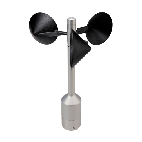
The sensor is designed for measuring the horizontal wind velocity in the field of meteorology, climate research, site assessment, and the measurement of capacity characteristics of wind power systems (power curves). The patented design is the result of long testing in the wind tunnel. The sensor features dynamic behaviour also at high turbulence intensity, minimal overspeeding, and a low starting values. It requires only low maintenance thanks to its low-inertia and ball-bearing cup star. The anemometer is equipped with electronically regulated heating to guarantee smooth running of the ball bearings and prevent icing of shaft and slot during winter operation.
|
Characteristics |
|
|---|---|
|
Physical functionality |
Optically-scanned cup anemometer |
|
Delivered signal |
Frequency output (pulse) |
|
Accuracy |
0.3 ... 50 m/s 1% of meas. value or < 0.2 m/s |
|
Linearity |
Correlation factor r between frequency f and wind speed y y = 0.0462 × f + 0.21 typical r > 0.999 99 (4 ... 20 m/s) |
|
Starting velocity |
< 0.3 m/s |
|
Resolution |
0.05 m wind run |
|
Distance constant |
< 3 m (acc. to ASTM D 5096 - 96) 3 m acc. to ISO 17713-1 |
| Turbulent flow | Deviation Δv turbulent compared with stationary horizontal flow -0.5 % < Δv < +2 % Frequency < 2 Hz |
| Inclined flow - mean deviation from cosinus line - Turbulence effect |
< 0.1 % (in range of ±20°) < 1 % (in the range up to 30% turbulence intensity) |
|
Wind load |
Approx. 100 N @ 75 m/s |
|
Operating range |
|
|
Measuring range |
0.3 ... 75 m/s |
|
Survival speed |
80 m/s (mind. 30 min) |
|
Permissible ambient conditions |
-50 ... +80 °C, all occuring situations of relative humidity |
|
Electrical data |
|
|
Output signal |
Form rectangle, 1082 Hz @ 50 m/s, supply voltage max. 15 V |
|
Electrical supply for optoelec. scanning |
Voltage: 3.3 ... 48 VDC (galvanic isolation from housing) Current: 0.3 mA @ 3.3 V (w/o external load) < 0.5 mA @ 5 V (w/o external load) |
|
Electrical supply for heating |
Voltage: 24 V AC/DC (galvanic isolation from housing) Idling voltage: max. 30 V AC, max. 48 VDC Power consumption: 25 W |
|
General |
|
|
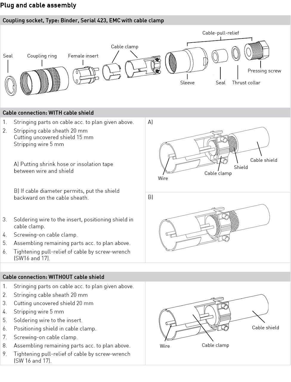
Connection |
8-pole plug-connection for shielded cable in the shaft |
|
Mounting |
on mast tube R1” |
|
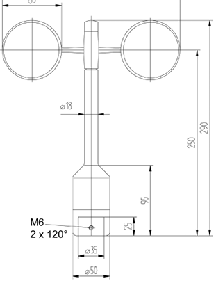
Dimensions |
290 x 240 mm |
|
Fixing boring |
35 x 25 mm |
|
Weight |
approx. 0.5 kg |
|
Material Housing Cup star |
Anodised aluminiun Carbon-fibre-reinforced plastic |
|
Type of bearings |
Metallic ball bearings |
|
Protection |
IP 55 (DIN 40050) |
|
Patent |
EP 1 398 637 DE 103 27 632 EP 1 489 427 |
|
EMC |
EN 61000-6-2:2001 (immunity) EN 55022:2001, Class B (interfering transmission) |
|
Manufacturer |
Thies |
| Sensor |
Plug Pin No.
|
Ammonit Cable Wire Colour | Meteo-40 | Supply Sensor |
|---|---|---|---|---|
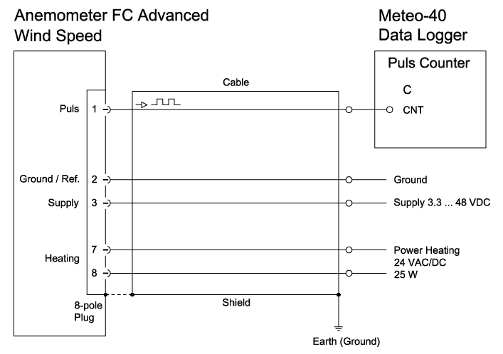
| Wind speed Pulse output |
1 |
white | CNT | |
| Supply | 3 | red | 9 ... 36 V* | |
| Ground | 2 | black | Main Ground | |
| Heating | 7 |
orange, orange | 24 V AC/DC | |
| 8 | violet, violet |
* Supply voltage for usage with Meteo-40 data loggers.
Cable type without heating: LiYCY 3 x 0.25 mm²
Cable type with heating wires: LiYCY 7 x 0.25 mm²
| Sensor carrier | Sensor | Shielding / Ground |
| Metallic met mast, grounded | Non-isolated mounting on the met mast (e.g. by using metallic brackets, holders, etc.) | Connect cable shield only at the side of the data logger to ground. |
| Metallic met mast, grounded | Isolated mounting at the met mast (e.g. by using non-metallic brackets, holder etc. or metallic brackets, holders etc. with isolated plastic adapters) | Connect cable shield at sensor plug and at the side of the data logger to ground. |
| Metallic met mast, non-grounded | Non-isolated mounting on the met mast (e.g. by using metallic brackets, holders etc.) |